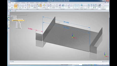
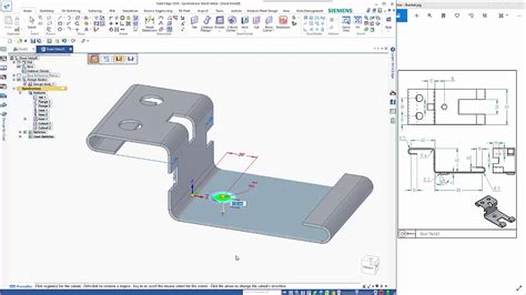
solid edge sheet metal flat pattern drawing Solution. Using the drawing view wizard select the sheet metal file (.psm) then . $34.65
0 · solid edge sheet metal design
1 · solid edge sheet metal cad
2 · solid edge design
3 · siemens sheet metal draft view
4 · show flattened pattern in draft
5 · how to show flattened patterns
6 · flat sheet metal draft view
7 · design sheet metal parts
Metal fabrication is a highly sought-after trade in a number of industries. As with many specific trades, metal fabrication takes time; and to learn the methods of working with metal, adequate .

1. Create part. using manually entered sheet values, or the gage table for reusable combinations of thickness, bend radius, and K factor (location of neutral axis). The K factor .I'm trying to create a drawing in the draft environment. This dft should have a top .Solution. Using the drawing view wizard select the sheet metal file (.psm) then .Design a sheet metal part. To meet unique sheet metal design challenges, like .
Solution. While a drawing view is attached to your cursor, go to the View Wizard -. .How can a drawing view of a flat pattern be placed when the sheet metal file is .Create 3D models, generate flat patterns, and perform simulation and analysis for .Download our Solid Edge sheet metal design whitepaper! The design of sheet .
I'm trying to create a drawing in the draft environment. This dft should have a top view, front view, right view, and a flat view with bendlines. Ok, make a new view with the "View Wizard" . Solution. Using the drawing view wizard select the sheet metal file (.psm) then select the radio button next to flat pattern.
solid edge sheet metal design
Design a sheet metal part. To meet unique sheet metal design challenges, like manufacturability, Solid Edge streamlines the entire sheet metal product development process, from CAD design through flat pattern and drawing development. Solution. While a drawing view is attached to your cursor, go to the View Wizard -. Drawing View Wiard Options. If your sheet metal file contains a flat pattern, there will be a Flat . How can a drawing view of a flat pattern be placed when the sheet metal file is inside of an assembly that has been place into draft? Solution To place a drawing view . Solid Edge 2024 Sheet Metal Flat Pattern Please visit www.siemens.com/solidedge.
Create 3D models, generate flat patterns, and perform simulation and analysis for sheet metal products such as enclosures, cabinets, brackets, panels, and other parts with Solid Edge sheet metal design software.You can create drawings of flattened sheet metal parts in the Draft environment. A special template can be applied when a flat pattern drawing is created. This template has tangent edges displayed so that the lines that represent the .
Download our Solid Edge sheet metal design whitepaper! The design of sheet metal parts require a specialized toolset due to manufacturing processes. We show you what you can expect from your CAD software.Use the Tools tab →Flat group→Flatten command in the Sheet Metal environment to create a flat pattern in the same file as the formed sheet metal part. When you flatten a sheet metal part with the Flatten command, a Flat Pattern feature is added to the PathFinder tab. If the sheet metal model changes, the flat pattern becomes outdated. Drawing View Wiard Options. If your sheet metal file contains a flat pattern, there will be a Flat Pattern radio button on the dialog that can be selected. Notes and References. Hardware/Software Configuration Platform: INTL64 OS: windows OS Version: 10_1809 Product: SOLID_EDGE Application: DRAFT Version: V219.0 Function: DRAWING_VIEWS Ref: 001 .
How to unfold a sheet metal part. Aug 29, 2019; Knowledge; Information. Title How to unfold a sheet metal part. URL Name how-to-unfold-a-sheet-metal-part . Here is a nice video showing how to unfold a sheet metal part commonly known as flat pattern in Solid Edge. Solid Edge Solid Edge Knowledge Base. Filter Feed Refresh this feed. Skip Feed . You can create a flatten (unbended) sheet metal view in the drafting. To create a flatten view in drafting: Activate the “Sheet Metal” application. Click the “Flat Pattern” command. (In the sheet metal application) Select the face on the sheet metal model to specify a reference face for flattening.In a sheet metal part, create a new configuration. In the FeatureManager design tree, do one of the following: Right-click Flat-Pattern and select Unsuppress.; Select Process-Bends and all of the features after it. Click Edit > Suppress > This Configuration to .
technology and Solid Edge Sheet Metal to speed design time and stream-line manufacturing. . current working drawings don’t reflect the entire sheet metal process, such as bend tables and flat patterns. Also since the shop floor cannot take advantage of manufacturing data present in 3D solid edge sheet metal tutorial.solid edge tutorial and free training videos for beginners.solid edge sheet metal flatten tutorials.how to flat sheet metal p.
solid edge sheet metal cad
Hi, I am inexperienced with SW sheet metal; I have inherited a bunch of drawings, and I can tell the views to use flat patterns, but when I do the edge flanges remain bent. Other sheet metal features are flattened, but not the edge flanges.
I need to pattern a sheet metal flat in draft mode. This is so I can create a DXF of a full sheet metal sheet of flats for laser cutting. . Siemens: Solid Edge . pattern in draft mode??? . Combining model dimensions in drawings. John_W2; Jun 7, 2021; Siemens: Solid Edge; Replies 0 Views 138. Jun 7, 2021. John_W2. Share: Facebook X (Twitter .
Sheet metal as far as I can tell works well if you’re going to bend a straight edge, but for roles parts and fabric patterns, not so helpful. . Funkf4rm • Upload file or drawing you are working off of. Should be pretty simple. Reply reply . Can anyone tell my why SOLIDWORKS exports that artifact with sheet metal flat patterns?flat pattern and drawing development. Unlike general-purpose CAD tools, Solid Edge includes sheet metal-specific features like emboss, dimple, drawn cutout, bead, contour flange, linear bends and etch. And with integrated applicati-ons for analysis, 2D nesting, NC programming, and related tasks, Solid Edge helps you accelerate design time, improveControls flat pattern treatment settings for the active sheet metal document. Changing these options once a flat pattern is generated causes a recompute of the flat pattern feature, or an update to the associative flat pattern if it was placed with the Insert Copy command. These tab options are available in the Solid Edge Sheet Metal environment.Hello! I'm currently a student working part-time in a small sheet metal manufacturing company. Right now, my job is to recreate parts that we have drawn in SolidEdge in SolidWorks. My problem is that every time I draw a part and flatten it, the dimensions in the flat pattern never match the reference drawing (+/- .010 tolerance).
Whenever you insert a sheet metal part into a drawing, SOLIDWORKS automatically creates a derived configuration in the part file for the flat pattern. When functioning normally, this derived configuration SHOULD have the flat pattern feature unsuppressed in the part’s feature tree, however it is easy to accidentally suppress/unflatten it.
To open this dialog box: With a part, assembly, or drawing open, click Tools > Options > Document Properties > Sheet Metal.. To show bend lines in flat patterns, do one of the following: Click View > Hide/Show > Sketches.; In the FeatureManager design tree, expand Flat-Pattern and Flat-Pattern(n).Right-click Bend-Lines and click Show.to transfer the sheet metal information. Form the help: “Transfers the sheet metal and flat pattern information from the original part to the mirrored part such as fixed face, grain direction, bend lines, and bounding box. Some sheet metal .i worked at a large company with a world-class sheet metal manufacturing plant attached. we were required to provide a flat pattern view with each sheet metal drawing, but dimensions were not required. the purpose here was to "prove" .
Complete, automated sheet metal design with Solid Edge. . Solid Edge streamlines the entire sheet metal product development process, from CAD design through flat pattern and drawing development. With integrated applications for analysis, NC programming, and other related tasks, Solid Edge helps you speed design time, improve quality, and . Find out how Solid Edge sheet metal design capabilities can help you to speed your design process Download our Solid Edge sheet metal design whitepaper! January 16, 2019 By Krystle Follick Tags: design for manufacturing design for manufacturing strategy efficiency in manufacturing manufacturing aspects production-related aspects simpler .
How do you place a drawing view of a flat pattern? Solution While placing the Drawing View in Draft, click on the Drawing View Wizard Options button on the command bar, then select the Flat pattern radial button from the dialog. . Product: SOLID_EDGE Application: DRAFT Version: V220.0 Function: DRAWING_VIEWS Ref: 002-7008933. KB Article ID .You can flatten all the bends of a sheet metal part at once. Creating a Sheet Metal Drawing. Now create a drawing of the sheet metal part. Start with an isometric view of the folded model, and then add a view of the unfolded model. Completing the Sheet Metal Drawing. Next, add a view of the unfolded model. A flat pattern view is automatically . With sheet metal designs, when you have more than one body, SOLIDWORKS will create separate flat patterns and cut lists on the FeatureManager Design Tree. But, when it comes time to create a 2D drawing, if you have a multibody sheet metal part, you will not see a flat pattern view by default when adding a model view onto the drawing. To show .Controls flat pattern treatment settings for the active sheet metal document. Changing these options once a flat pattern is generated causes a recompute of the flat pattern feature, or an update to the associative flat pattern if it was placed with the Insert Copy command. These tab options are available in the Solid Edge Sheet Metal environment.
I used the sheet metal edge flange feature to create this. The slits shown on the corner are needed so we can bend this in our press brake. . When you're in the drawing, expand the flat pattern in your feature tree and you can right click the Bend Lines and select Show. If they don't appear, make sure that Bend Lines is selected in the View .Open the sheet metal part for which you want to add a drawing. Click Make Drawing from Part/Assembly (Standard toolbar), and click OK to open the drawing sheet. Select a format or click OK to use the default format. From the View Palette, drag the Flat pattern to the drawing sheet.With sheet metal designs, when you have more than one body, SOLIDWORKS will create separate flat patterns and cut lists on the Feature Manager Design Tree. But, when it comes time to creating a 2D drawing, if you have a multibody sheet metal part, you will not see a flat pattern view by default when adding a model view onto the drawing. There are several ways to get Sheet Metal Bend Lines to show (or not show) in a SOLIDWORKS drawing. This quick tutorial explains how. Where to Find Bend Lines. First, we need to know where the Bend Lines are stored/created/saved. In a part generated with the Sheet Metal tools, Bend Lines are stored in the Flat Pattern feature.

solid edge design
siemens sheet metal draft view
ASC Building Products' corrugated metal roof panels are light gauge, exposed fastener panels for agricultural and residential roofing applications.
solid edge sheet metal flat pattern drawing|how to show flattened patterns