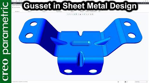
creo sheet metal gusset In this tutorial, we can learn how to place punch form easily byLocating manually with constraints.Using a Component Interface. Raco had the "536-BOX" which is a sidecar that attaches to any of their 2.5" deep gangable boxes. So two of the 519 or similar gangable old-work boxes to give you the 2-gang, plus a sidecar or two for a bit of extra box-fill could do it.
0 · sheet metal gusset tutorial
1 · sheet metal gusset design
2 · how to create a gusset
3 · creo sheet metal tutorial
4 · creo sheet metal gusset tutorial
5 · creo parametric gusset design
$110.49
Sheet metal gussets are provided to avoid unbending the Sheet metal part under load conditions.In this video, we will learn how to design a gusset in Creo pa. In this tutorial, we can learn how to place punch form easily byLocating manually with constraints.Using a Component Interface.
There are four Form tools: • Punch Form —Molds the sheet metal geometry by assembling a punch form model from a library of standard or user-defined models. • Die Form —Molds the .You can create a Gusset on a model following the template shown below: The dimensions in the graphic are defined as follows: 1. Click Mold Feature and then, in the Plastic Feature group, . Hi Everyone, Here I have shown Gusset feature in CREO.Electrical Wire Harnesshttps://studio.youtube.com/video/IoeoxRxDZAc/editPart time .
Check out this video on Creo Sheetmetal Design from PTC Application Engineers Presenters: Lino Tozzi (Technical Specialist, Fellow) and Ryan Butcher It is quite common to find a gusset of sorts in the corner(bend region) of sheet metal parts to stiffen the part. To accomplish this, we'll create a custom form tool (or copy the one attached) to define the shape of the gusset.Creo Elements/Direct Sheet Metal creates a new 3D sheet metal part. Options specific to Solid include: • Cut replaces an existing bend edge by a cut edge and divides the selected part into two parts.Sheet metal gussets are provided to avoid unbending the Sheet metal part under load conditions.In this video, we will learn how to design a gusset in Creo pa.
In this tutorial, we can learn how to place punch form easily byLocating manually with constraints.Using a Component Interface.There are four Form tools: • Punch Form —Molds the sheet metal geometry by assembling a punch form model from a library of standard or user-defined models. • Die Form —Molds the sheet metal geometry by assembling a die form model from a .
You can create a Gusset on a model following the template shown below: The dimensions in the graphic are defined as follows: 1. Click Mold Feature and then, in the Plastic Feature group, click Create. The Plastic Feature Browser opens. 2. Double-click Gusset in the browser. The Gusset dialog box appears. 3.Hi Everyone, Here I have shown Gusset feature in CREO.Electrical Wire Harnesshttps://studio.youtube.com/video/IoeoxRxDZAc/editPart time earning videosLink fo. Check out this video on Creo Sheetmetal Design from PTC Application Engineers Presenters: Lino Tozzi (Technical Specialist, Fellow) and Ryan Butcher
It is quite common to find a gusset of sorts in the corner(bend region) of sheet metal parts to stiffen the part. To accomplish this, we'll create a custom form tool (or copy the one attached) to define the shape of the gusset.Creo Elements/Direct Sheet Metal creates a new 3D sheet metal part. Options specific to Solid include: • Cut replaces an existing bend edge by a cut edge and divides the selected part into two parts.

Sheetmetal Design using Creo Parametric is a comprehensive training course that teaches you how to create sheet-metal parts in Creo Parametric. The course builds upon the basic lessons you learned in Introduction to Creo Parametric and serves as the second stage of learning.Converting STEP or IGES imports to legitimate Creo Sheet metal parts for manufacturing; Flexible modeling tools specifically related to Creo sheet metal imports; Working with sheet metal vendors and preparing a deliverable to obtain the desired results and tolerancesSheet metal gussets are provided to avoid unbending the Sheet metal part under load conditions.In this video, we will learn how to design a gusset in Creo pa.
sheet metal gusset tutorial
In this tutorial, we can learn how to place punch form easily byLocating manually with constraints.Using a Component Interface.There are four Form tools: • Punch Form —Molds the sheet metal geometry by assembling a punch form model from a library of standard or user-defined models. • Die Form —Molds the sheet metal geometry by assembling a die form model from a .
sheet metal fabricators in texas
You can create a Gusset on a model following the template shown below: The dimensions in the graphic are defined as follows: 1. Click Mold Feature and then, in the Plastic Feature group, click Create. The Plastic Feature Browser opens. 2. Double-click Gusset in the browser. The Gusset dialog box appears. 3.Hi Everyone, Here I have shown Gusset feature in CREO.Electrical Wire Harnesshttps://studio.youtube.com/video/IoeoxRxDZAc/editPart time earning videosLink fo.
Check out this video on Creo Sheetmetal Design from PTC Application Engineers Presenters: Lino Tozzi (Technical Specialist, Fellow) and Ryan Butcher It is quite common to find a gusset of sorts in the corner(bend region) of sheet metal parts to stiffen the part. To accomplish this, we'll create a custom form tool (or copy the one attached) to define the shape of the gusset.Creo Elements/Direct Sheet Metal creates a new 3D sheet metal part. Options specific to Solid include: • Cut replaces an existing bend edge by a cut edge and divides the selected part into two parts.Sheetmetal Design using Creo Parametric is a comprehensive training course that teaches you how to create sheet-metal parts in Creo Parametric. The course builds upon the basic lessons you learned in Introduction to Creo Parametric and serves as the second stage of learning.
sheet metal gusset design

how to create a gusset
Located in Belle Vernon, PA. Willing to travel.
creo sheet metal gusset|creo parametric gusset design