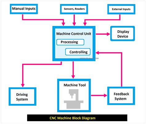
block diagram of cnc machine tool A block diagram is a critical tool to understand complex systems like CNC machines. In its most simplistic definition,a block diagram is a flowchart that displays how different elements of a . Our Flushfloor Our Flushfloor, Raisedfloor and Underfloor Trunkings caters to different needs of the Floor Trunking market.
0 · structure of cnc machine tools
1 · schematic diagram of cnc machine
2 · main components of cnc machine
3 · cnc machining process flow chart
4 · cnc machine parts list pdf
5 · cnc machine part names
6 · cnc machine labelled diagram
7 · basic elements of cnc machine
According to UL 870, a 24" x 24" x 72" enclosure must be 12 gauge. I found a code requirement for minimum thickness of cutout boxes but I dont believe the article applies to troughs. Surely this isnt acceptable protection for seven runs of 500kcmil (no OCP) feeding a 2500 amp switchgear.
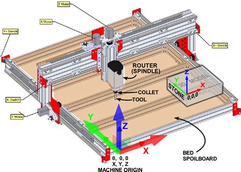
CNC machines consist of several key components and elements that contribute to their functionality and efficiency. Here, we will explore the primary parts of CNC machines and the elements they incorporate.
In this article, we will explore the main parts of a CNC machine and explain the CNC block diagram in simple terms. 1. Machine Control Unit (MCU) The Machine Control Unit is the brain of the CNC machine. It reads the G-code (the .A block diagram is a critical tool to understand complex systems like CNC machines. In its most simplistic definition,a block diagram is a flowchart that displays how different elements of a .
A computer numerical control (CNC) system, showcasing the block diagram of cnc machine, consists of three basic components: CNC software which is a program of instructions, a machine control unit, and processing equipment, .In this comprehensive guide, we will explore the ins and outs of CNC machine schematic diagrams and provide a detailed analysis of each component. Table of Contents: 1. What is a .
In this blog post, we will delve into the intricacies of CNC machines through a comprehensive block diagram. We will explore the different components and their functionalities, shedding .This document describes the key components of a CNC machine. It discusses 13 parts, including the machine control unit that interprets G-code and controls the machine, the driving system that moves tools along axes using motors and .(iii) Machine Tool: A CNC machine tool always has a slide table and a spindle to control of the position and speed. The machine table is controlled in X and Y axis direction and the spindle is controlled in the Z axis direction. CNC machine tools operate based on input part machining programs. These programs contain information about the relative motion trajectories between the machine tool’s cutting tool and the workpiece, process parameters (such as feed rate, spindle speed, etc.), and auxiliary movements.
CNC machines come in many different configurations, but the most common are CNC mills and CNC lathes. CNC lathes are better suited to processing cylindrical parts whereas mills can be used on flat, curved, or angular parts. This .
CNC machines consist of several key components and elements that contribute to their functionality and efficiency. Here, we will explore the primary parts of CNC machines and the elements they incorporate.In this article, we will explore the main parts of a CNC machine and explain the CNC block diagram in simple terms. 1. Machine Control Unit (MCU) The Machine Control Unit is the brain of the CNC machine. It reads the G-code (the programming language for CNC) and converts it into electrical signals that control the machine's movements.A block diagram is a critical tool to understand complex systems like CNC machines. In its most simplistic definition,a block diagram is a flowchart that displays how different elements of a system interact and function together.
A computer numerical control (CNC) system, showcasing the block diagram of cnc machine, consists of three basic components: CNC software which is a program of instructions, a machine control unit, and processing equipment, also called machine tool.
In this comprehensive guide, we will explore the ins and outs of CNC machine schematic diagrams and provide a detailed analysis of each component. Table of Contents: 1. What is a CNC Machine? 2. Importance of Schematic Diagrams. 3. Basic Components of a CNC Machine\ a. Controller\ b. Motors\ c. Spindle\ d. Power Supply\ e.In this blog post, we will delve into the intricacies of CNC machines through a comprehensive block diagram. We will explore the different components and their functionalities, shedding light on the amazing capabilities of these high-tech tools. Block Diagram Overview:This document describes the key components of a CNC machine. It discusses 13 parts, including the machine control unit that interprets G-code and controls the machine, the driving system that moves tools along axes using motors and screws, and .(iii) Machine Tool: A CNC machine tool always has a slide table and a spindle to control of the position and speed. The machine table is controlled in X and Y axis direction and the spindle is controlled in the Z axis direction.
CNC machine tools operate based on input part machining programs. These programs contain information about the relative motion trajectories between the machine tool’s cutting tool and the workpiece, process parameters (such as feed rate, spindle speed, etc.), and auxiliary movements. CNC machines come in many different configurations, but the most common are CNC mills and CNC lathes. CNC lathes are better suited to processing cylindrical parts whereas mills can be used on flat, curved, or angular parts. This .CNC machines consist of several key components and elements that contribute to their functionality and efficiency. Here, we will explore the primary parts of CNC machines and the elements they incorporate.
6awg junction.box
In this article, we will explore the main parts of a CNC machine and explain the CNC block diagram in simple terms. 1. Machine Control Unit (MCU) The Machine Control Unit is the brain of the CNC machine. It reads the G-code (the programming language for CNC) and converts it into electrical signals that control the machine's movements.A block diagram is a critical tool to understand complex systems like CNC machines. In its most simplistic definition,a block diagram is a flowchart that displays how different elements of a system interact and function together.A computer numerical control (CNC) system, showcasing the block diagram of cnc machine, consists of three basic components: CNC software which is a program of instructions, a machine control unit, and processing equipment, also called machine tool.In this comprehensive guide, we will explore the ins and outs of CNC machine schematic diagrams and provide a detailed analysis of each component. Table of Contents: 1. What is a CNC Machine? 2. Importance of Schematic Diagrams. 3. Basic Components of a CNC Machine\ a. Controller\ b. Motors\ c. Spindle\ d. Power Supply\ e.
In this blog post, we will delve into the intricacies of CNC machines through a comprehensive block diagram. We will explore the different components and their functionalities, shedding light on the amazing capabilities of these high-tech tools. Block Diagram Overview:This document describes the key components of a CNC machine. It discusses 13 parts, including the machine control unit that interprets G-code and controls the machine, the driving system that moves tools along axes using motors and screws, and .

structure of cnc machine tools

$20.99
block diagram of cnc machine tool|cnc machining process flow chart