sheet metal bend radius chart Learn how to choose the right bend radius for sheet metal fabrication based on the thickness and material of the sheet. See reference tables for steel and aluminium and tips for bend orientation and design. $26.99
0 · sheet metal minimum bend length
1 · sheet metal inside bend radius
2 · sheet metal bend radius standard
3 · sheet metal bend radius guide
4 · bending steel plate minimum radius
5 · bend radius vs material thickness
6 · 304 stainless steel bend radius
7 · 304 stainless minimum bend radius
When it comes to hiding a utility box, a fence is perhaps the quickest solution. A fence not only hides a utility box, but it also creates a barrier that can help prevent children from playing near these high-voltage areas. A fence is also .
It is most economical to use a single bend radius throughout the design, but if necessary, you can utilize multiple radii. Use this document to choose values that are both manufacturable and meet your needs. If you need help choosing a value, contact us at [email protected] 1-866-849-3911 and we can help. . See moreGeometry of tooling imposes a minimum bend dimension. The diagram shows one such mechanism. Refer to the chart for values for folder as well as various press brake tooling . See moreWe’ve broken down our minimum bend radii into two values: minimum hole distance and minimum flange distance. Minimum hole distance specifies how far a hole must be placed . See moreNote 1: The bend radius you select may not be available if the geometry of the part will not allow us to bend with the specific tooling required to achieve that radius. If your bend radius . See more
Learn how to choose the right bend radius for sheet metal fabrication based on the thickness and material of the sheet. See reference tables for steel and aluminium and tips for bend orientation and design.Find the recommended minimum bend radius for different thicknesses and types of sheet metal materials. The charts show the bend radius measured to the inside of the bend and the grain .
Learn how to calculate and optimize the bend radius of metal parts for different materials and thicknesses. Find a comprehensive bend radius chart with values for inside die, punch radius, V width radius and angle. Bend Radius Chart for Mild Steel, Stainless Steel & Aluminum. When considering sheet metal design, it’s important to understand how the bend radius affects your choice of materials. In this section, we’ll discuss some .Sheet Metal Bend Radius Guidelines Here are a few key concepts to know about designing for sheet metal Brackets, covers, cabinets, chassis, electrical enclosures.The tables below show bend radii and minimum bend sizes for materials and tooling combinations stocked by Protocase. We go beyond the general rules of sheet metal bending, as our .
The Sheet Metal Bend Radius Chart is an indispensable resource for anyone involved in sheet metal fabrication. By providing detailed information on material properties, minimum bend .90-DEGREE COLD FORMING OF SHEET. without fracturing in a standard press brake with air bend dies. Other types of b. nding operations may require larger radii or permit smaller radii. .This is a step-by-step guide. First, you need to determine the radius and bend angle. Use the following formula: Bend allowance = (p/180 x Bend angle x (Radius x K-Factor + Thickness). . Table of Contents. 1 Common Bend Radius Design Mistakes; 2 Sheet Metal Part Design for Manufacturing Tip. 2.0.1 UNABLE TO UNFOLD PART, SHEET METAL BEND RADIUS ISSUE RESOLVED; 3 How to .
90-DEGREE COLD FORMING OF SHEET The radii listed are the minimum recommended for bending sheets and plates without fracturing in a standard press brake with air bend dies. Other types of bending operations may require larger radii or permit smaller radii. The minimum permissible radii will also vary with the design and condition of the tooling.
sheet metal minimum bend length

sheet metal inside bend radius
One of the biggest challenges in sheet metal fabrication is ensuring the accuracy of the unfold dimensions after bending. This involves accounting for various factors such as material type, thickness, bend radius, and bend angle. .Bending Radius Bending Radius refers to the minimum radius that can be applied to a sheet metal component where its flange originates from. Bending radii are usually dictated by available tooling, and for quick and effective design work it is recommended to speak with manufacturers so that design can be done around their standard operating procedures as well as available tooling.

Air Force Bending Chart. The Air Force Bending chart is a chart showing the tonnage used for bending different thickness sheet metal. It is useful for sheet metal designers as it specifies the bend radius and tooling to be used for different thicknesses. It is shown here for mild steel.
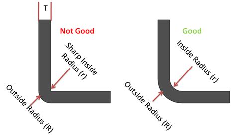
Instructions for Optimal Use: Input Material Thickness and Inner Radius: • Enter the precise sheet thickness and desired inner bend radius. • The calculator will instantly provide the K-factor, Y-factor, and neutral layer position, crucial for accurate bending calculations. The bend’s outer edge would crack if it exceeds the minimum bend radius which is typically specified according to the metal sheet thickness (t) like 1t, 2t, 3t etc. A typical recommendation is 1t for all sheet metal parts, which means the smallest bend radius should be at least equal to the sheet thickness.Bend Radius - As a rule, inside bend radius should be equal to material thickness. When the radius is less than recommended, this can cause material flow problems in soft material and fracturing in hard material. Bend Relief - When a bend is made close to an edge the material may tear unless bend relief is given. Figure "A" shows a torn part.
The minimum sheet metal bending height should be calculated as 2 times the thickness of the sheet metal plus the bending radius, i.e., H ≥ 2t + R. As illustrated in the accompanying figure, if the bending height is too low, the sheet metal is prone to deformation and twisting during the bending process , leading to suboptimal part shape and . Sheet metal bending can be done using many methods. We discuss those along with springback, bend allowances, k factor, design tips etc. . The imperial version of the bending force chart can be found here. . constant; ir – inside radius (mm); t – sheet thickness (mm) Bend allowance formulas: For bends between 0 and 90 degrees, the .The bend radius is a critical parameter in sheet metal fabrication, dictating the minimum radius one can bend a metal sheet without significant deformations. Calculating the correct bend radius is essential for ensuring the structural integrity and aesthetic of the finished product. Calculating Bend Radius in Air Forming
Sheet Metal Bending Calculation. Bend Allowance (BA) BA = [(0.017453 × Inside radius) + (0.0078 × Material thickness)] × Bend angle, which is always complementary. The length of the neutral axis is calculated as a bend allowance, taken at . The minimum inside sheet metal bend radius shows the smallest radius that’s possible in an air bend, but your machines may not be able to handle it. . Then I’d multiply this answer by the material thickness: 0.75 × 0.5 = 0.375 in. However, a bend allowance chart I have from our press brake manufacturer gives different information. For 0. . IV. Press Brake Bend Radius Calculation. The 8 times rule is a general guideline for determining the V-shaped die opening, suggesting that the V-die opening should be 8 times the material thickness. However, there is no .
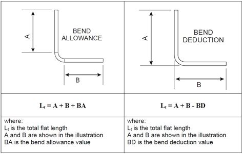
where: BA is the bend allowance; B< is the bend angle; IR is the inside radius; MT is the material thickness; The K-Factor is a dimensionless value and typically ranges between 0 and 0.5 for most sheet metal materials and .Bending is a fundamental process in sheet metal working that involves deforming a metal workpiece into a desired shape by applying force between two tools by a press brake: an upper tool (known as a punch) and a bottom tool (known as a . A sheet metal bend radius chart is a valuable tool that provides engineers and fabricators with essential information. It typically lists various materials and their corresponding recommended bend radii. Think of it as a cheat sheet for ensuring your metal sheets stay intact during the bending process. 3. The Rule of Thumb for Sheet Metal Bend . With this chart, you can save time and increase efficiency in your bending process.. Additionally, our press brake tonnage calculator can assist you in calculating the required bending force for your specific sheet metal product.. We understand the importance of selecting the most appropriate V-opening, and our chart shows the optimum relationship between metal thickness .
To calculate the sheet metal bend allowance, factors such as plate thickness, bending angle, internal radius, K factor, and others must be taken into account. The sheet metal bend deduction can be obtained once the bend allowance is known. You can either use a formula or a bend allowance chart to calculate the bend allowance.
Depth: The depth of your relief should be at least the material thickness + the bend radius + .02” (0.5mm) measured from the outside of your bend. That extra .02” provides just a little added clearance. . How to design bend reliefs for sheet metal with CAD software. There are two common ways to add bend relief to your design. One way is .How to calculate tonnage, internal radius and other bend parameters. This tool allows you to determine tonnage, internal radius, V-die opening and minimum flange.You just have to insert the characteristics of the sheet metal to be bent.Assuming you used an inside bend radius smaller than the material thickness, the K-factor (or neutral factor, if you prefer) in our cheesy example would be 0.33 for an air bend and 0.42 for a bottom bend, both gradually increasing to 0.5 for larger bend radii. Features of sheet metal bending design Bending is typically done with a press brake mechanism in a suitable die size. If your sheet metal manufacturing designs has bends, follow the following design rules. 1. Maintain a uniform bend radius, the minimum radius at which a material can be bent without causing damage, cracking, or deforming. 2.
The bend’s outer edge would crack if it exceeds the minimum bend radius which is typically specified according to the metal sheet thickness (t) like 1t, 2t, 3t etc. A typical recommendation is 1t for all sheet metal parts, which means the smallest bend radius should be at least equal to the sheet thickness. The bending deduction in Solidworks is only used for the calculation of 90-degree bends in sheet metal. However, it can also be used for the calculation of non-90-degree sheet metal unfolding, but the bending deduction value for non-90-degree bending needs to be used according to the bending coefficient table.

So it seems I need to do the following: 1) Set up a rule that tells inventor that when using this specific sheet metal style to use the material thickness for all bend angles that are not 90degress 2) For all other bends to use the radius from the provided bend table 3) Edit the a custom unfold rule to include the kfactor, bend radius, bend .
sheet metal bend radius standard

sketch driven sheet metal part
$21.99
sheet metal bend radius chart|sheet metal bend radius guide